 Pellentesque adipiscing leo condimentum enim ullamcorper pretium. Aenean gravida, libero nec convallis ornare, massa odio.
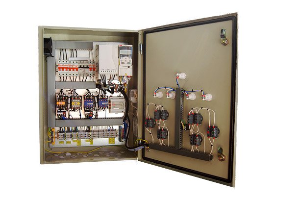
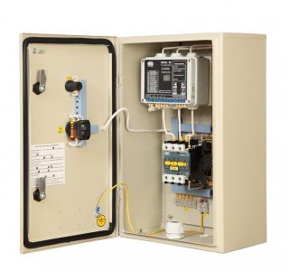
Control station of pumping units of the second and third lifting levelsStation is designed for automatic and manual control of a group of pumping units with asynchronous electric motors in quantity from two to six, with power of 315 kW each, operating in the cold or hot water supply systems in order to maintain the predetermined pressure in the main pipe. |
|
Monitoring and remote control system for pumping stationsControl and visualization system in SCADA Trace Mode 6 is designed for:
The system is focused on the use in conjunction with the control stations of pumping units (CSPU). Due to directivity of the SCADA system on solution of specific targets, the flexibility and functionality of control of the water supply objects have been reached. Now, there is no need of frequent visits of the engineers to the site for commissioning works. Fine adjustment of the station could be performed from the control panel. Test version of the system software (with limited functionality) is available. |
Separate components
Monitoring system of remote pressure sensorsMonitoring system of the remote pressure sensors ensures the possibility of operation of the control station of pumping units according to the parameters of these sensors. |
Control systems of rotary gates and slidesControl of shutoff and control valves is performed in the automatic mode and remotely by the operator. |
Control moduleofpumpingunitsIt is designed to maintain the predetermined pressure in the main pipe due to changes of the capacity of regulated pump and connection of the additional pump. |
Control station of pumping units of the second and third lifting levels
- Functional purpose
- Composition of the control stations
- Basic modes of operation
- Version
- Control station of pumping units ensures
- Designation diagram of control stations of the second and third lifting levels
- Basic functions (Table)
- Distinctive features of the station:
- Structural diagram of the control station of a group of three pumping units (Diagram)
Functional purpose
Station is designed for automatic and manual control of a group of pumping units with asynchronous motors in quantity from two to six, with power of 315 kW each, operating in the cold or hot water supply systems in order to maintain the predetermined water pressure in the main pipe.
Control stations have two model ranges: CSPU – automatic control stations of pumps and SPD – station of pumps’ drive. Their differences are stated in Table 1.
Composition of the control stations
1. Frequency converter, included in the pressure control circuit, which performs control of voltage and currents, having resistance to short-circuits, and provides control of the capacity of pumps.
2. Programmable logic controller, which provides the implementation of the predetermined control algorithm; implements monitoring and control functions of the frequency converter and a group of magnetic actuators.
3. Programmable measuring controller that implements the predetermined control algorithm and is provided with the electronic display of indication of the current and predetermined setpoint of the controlled parameter (pressure). It implements the PID-control functions and fuzzy-logic.
4. Flow-control valve (low-frequency filter), which protects the frequency converter from the effects of changes of parameters of supply voltage.
5. Automatic circuit-breakers according to the quantity of control units and pumping units.
6. Group of magnetic actuators of power commutation/switching with the overheat protection relays of the electric motors of pumps.
7. Remote pressure sensor.
8. Pressure sensors-relays.
Basic modes of operation
- Automatic
- Standby mode1
- Standby mode 2
- Manual
In the automatic mode, the station performs control of the following coordinates:
1. Determination of the number of pumps in operation. Maintaining of the predetermined pressure in the main pipe is carried out by cascade connection, i.e. chain connection of pumps. The number of pumps required for operation is determined automatically.
2. Frequency regulation of the last of the energized pumps for more accurate maintenance of pressure, and for reduction of hydraulic impacts in the main pipe and current rushes in the network.
3. Set point of pressure for night mode. During the specified period of time the station will automatically switch to the second set point of pressure maintenance. This mode is called "night" mode. Switching command is given by the control processor. Thus, all-night long the control system allows to reduce pressure in the control point while ensuring the required pressure in the common main pipe.
4. Timing of switching on of the additional pump depending on the pressure level in the main pipe (option - only for SPD stations).
5. Transition to the relay mode depending on the state of the frequency converter and sensor.
Control station could operate with different types of sensors: pressure, flow, temperature, etc., having standard outputs of current or voltage. Setting of the sensor type is performed from the measuring controller panel.
Control station has two potential free inputs, that allows regulation as for the difference of readings of two sensors.
Setting of the station as for the parameters of the pipelines is performed from the front panel of the control cabinet by changing the parameters of the digital measuring controller.
Algorithm of switching on of additional pumps. Before switching on of each subsequent pump, the controlled pump is forced out to full capacity; then, from the rotation state it is switched directly to the supply main. After switching the pump, the frequency converter produces a smooth start of the next, according to priority, serviceable pump permitted for operation.
Algorithm of switching off of the pumps. Switching off of the pumps is performed in reverse order. Controlled pump is transmitted into the mode of minimum capacity and disconnected from the converter. Previous pump, operating directly from the network, is disconnected from it and in the autorotation mode, connected to the output of the frequency converter. Therewith, the modulation mode of the converter is switched on that frequency of rotation of the pumping unit motor, which maintains a predetermined pressure in the main pipe ("flying restart" mode of rotating motor).
Switching on and off of the additional units, implemented in the control station, minimize the hydraulic impacts in the main pipe.
Control station has the possibility to configure the parameters of the two types of pipe lines.
The first type of lines is "long" lines, with which, as a rule, the stations of the 2d ... 3d lifting levels operate. Such lines are characterized, above all, by large extension, which determines the long-term transient processes. These lines are characterized by long-period wave oscillations. When operation with lines of large extension, the control station has a reduced sensitivity to such vibrations and, consequently, an increased response time to changes of pressure settings. This configuration avoids the "swing" of the control station in the event of long-period oscillations in the pipeline ("direct" and "reverse" wave).
The second type of lines is "short", with which, as a rule, the stations of the 3d ... 4th lifting levels operate, used in the "pumping" in the vicinity of the consumer (home, technological objects, etc.). In this mode, the control system has a high sensitivity to changes of pressure, i.e. short tome of response to the control signal.
Control station performs monitoring of the state of pumps as for the following parameters:
1. Increase of current consumed by the electric motor is higher than the set value.
2. Absence of differential pressure in the pump unit (option).
3. Reduction of consumed current below the set value ("no load" of electric motor - option).
Station automatically controls the input and output main pipes.
Control of the input main pipe is realized by commands of the pressure sensor-relay in order to avoid "dry running" of pumps, i.e. operation of system from the supply main with pressure below the predetermined value.
Control of the output main pipe is carried out according to time interval of operation of all pumps in maximum capacity mode and pressure level below the predetermined value.
Station provides automatic protection against sensor breakage with simultaneous indication of this state.
To produce uniform resource of the pumps, the station automatically carries out their alternation, i.e. in the specified period of time, reference time of pumps moves in the direction of increasing of their serial number.
In case of failure of the frequency converter, the station automatically passes into the standby mode of operation.
Standby mode of operation is determined by the operator prior to switching on of the station.
In standby mode 1, only one energized and operative pump is switched on for a permanent operation from the network.
In standby mode 2, maintenance of the value of predetermined pressure by controlling the quantity of connected pumps is realized. Switching on of pumps is performed with relay by the process controller according to the commands of programmable measuring controller without participation of the frequency converter, i.e. control is carried out only acc. to one coordinate. In this mode, alternation of sequence of the pumps’ operation is performed once per three days.
Thus, the station has an additional backup control channel, which increases its reliability.
In standby modes 1 and 2, the station realizes control of the input main pipe and in the standby mode, 2 - control of the output main pipe as well as control of the sensor state.
In standby mode 1 and 2 electric drive of gate valves could be controlled. Valves are opened after activation of the pump and closed before its stop. Information on the opening and closing of the valves is removed from the "dry contacts" of the limit switches.
In manual mode, the operator switches on the pump to the network by pressing the appropriate buttons.
Version
System is located in the electrical control cabinet having degree of protection not less than IP54, provided with fittings of indication and control on the front side. Cabinet is equipped with the control system of the fan blowing, which is adjustable as for temperature.
Monitoring and control system of low level is implemented in service at the station (see. Table 1).
Station could be equipped with the monitoring and control system of high level. The equipment is manufactured on the additional application.
On the separate request, the control station could be supplied with an intelligent control panel with two-line LCD-display, allowing to perform a deep adjustment of system, as well as control its current state.
Control station is supplied completed with a pressure sensor (or another sensor on the additional application), as well as a pressure sensor-relay. On a separate application, the control station could be equipped with sensors-relays of relation of pressure to the number of pumping units.
Documentation for installation, system adjustment at site, as well as for carrying out of repairs during the operation, is completed in the station set.
Control station of the pumping unit ensures:
• Saving of consumed electricity (not less than 50 ... 65%) and reduction of water consumption.
• Limitation of inrush currents in the network.
• Increase of the resource of electric motors of pumps.
• Elimination of hydraulic impacts, reduction of accidents and losses related to them.
• Availability of the backup channels.
• Availability of display system.
• Reduction of the quantity of duty and maintenance personnel.
Basic functions
Table 1
| N | Functions | CSPU-Х-ХХ | SPD-Х-ХХ М |
| 1 | Control in the coordinate frame: | ||
|
+ | + | |
|
+ | + | |
|
- | + | |
|
+ | + | |
| 2 | Switching of controlled pump directly to the network from the running state at insufficient water pressure level in the main pipe and regulation of the next pump according to priority. | + | + |
| 3 | Control of state of the inlet and outlet main pipes. | + | + |
| 4 | Transition of the control station into a relay operation mode in case of failure of the frequency converter. | + | + |
| 5 | Setting of the first from the running pumps by the operator as well as prohibition of control by any of pumps. | + | + |
| 6 | Setting of the pressure level in the main pipe for the day and night modes on the visual display of measuring controller by the operator | + | + |
| 7 | Control of state of the electric motor as for consumed current. | + | + |
| 8 | Automatic adjustment of parameters of the station depending on parameters of the controlled object to reduce the number of switching of the pumping units (with the exception of negative points of the regulation line). | - | + |
| 9 | Availability of monitoring system with indication and control from the computer (on order). | + | + |
| 10 | Control of operation of the station and generation of signals:
|
+ | + |
| 12 | Electromagnetic and thermal protection of the frequency converter and motors. | + | + |
| 13 | Repeated automatic connection to the supply main after voltage failure. | + | + |
Distinctive features of the station:
1. Smooth start of each pump unit at their series connection.
2. Frequency regulation by each pump unit.
3. Connection the controlled pump to the network from the rotation state ("shock-less" connection).
4. Flying restart of rotating pump in mode of series disconnection of pumps at the rotation frequency, necessary for pressure maintenance.
5. Connection of an additional pumping unit depending on pressure in the main pipe, switching off – by the signal of PID-controller.
6. Availability of the relay operation mode, ensuring the maintenance of the predetermined pressure in case of failure of the frequency converter (two stations - the frequency and relay in one).
7. Original algorithm of monitoring of capacity of the pumping units, excluding their false rejection, as well as converter failure due to load failure.
8. Protection against sensor breakage.
9. Estimated time of switching on and off of the additional pumps depending on the current pressure value (option).
10. Availability of setting of night mode, providing additional saving of electricity.
11. Possibility to set up 20 settings of pressure for day mode (option).
12. Possibility of correction of the value of predetermined pressure by signals of the remote sensor installed in the control point (option).
13. Possibility of setting the parameters of the "long" (stations of 2d to 3d-lifting level) and "short" lines (stations of 3d-4th lifting level) of pipelines.
14. Availability of inlet flow-control valve (LF filter).
15. Distributed structure of system construction, providing a functional redundancy, as well as possibility to operate with various frequency converters without changing the software.
16. Digital display of values of current and predetermined pressure.
17. Availability of two potential free inputs for connection of analog sensors, enabling operation with pressure difference.
18. Possibility to read information about parameters recorded by two sensors in digital form via 485 interface into the monitoring system of high level.
19. Possibility of implementation of the monitoring and remote control system in the process controller.
20. Possibility of the direct monitoring and control of the station via 232 interface of the physical line.
21. Switching on and off of the fan blowing, that is adjustable as for temperature.
22. Consideration of electromagnetic compatibility of the equipment.